Generator Schematic : Schematic Diagram Of Flue Gas Generator In Greenhouse Source Download Scientific Diagram / Gen = generator end only :
bymagaresper•
0
Generator Schematic : Schematic Diagram Of Flue Gas Generator In Greenhouse Source Download Scientific Diagram / Gen = generator end only :. If you are installing a standby generator in order to have some electrical power to your home in the event of a utility power outage, it is important that you understand how to properly install a transfer switch. It uses flash circuits from disposable cameras to power the coil. The dashboard is supplied by the terminal blade 15/54 via a 5 amp fuse. Generator wiring diagram and electrical schematics: This circuit is designed with various electrical and electronic.
I believe that it would need to have a resistor, or potentiometer, between the motor and the generator. Champion 5500 watt generator cotswoldwool co. A consulting electrical engineer can help determine the optimal configuration to meet your facility's needs. The be24 generator auto start circuit diagram is a simple and intuitive diagram. It will generate output 3 waveform, sine wave signal, triangle, and square wave signals.
Impulse Voltage Generator Marx Generator Circuit Diagram Working Principle And Applications from circuitdigest.com Ecu = engine control :automatic engine start. Click on the link for your model number to open a.pdf version of the generator manual. Such a set is commonly known as genset. Decide whether a remote switch to start and stop the generator is important or whether using the switch on the generators fascia will be. Op amp tone generator circuit. Egs = electronic governor system. If you are installing a standby generator in order to have some electrical power to your home in the event of a utility power outage, it is important that you understand how to properly install a transfer switch. I am just trying to figure out the proper schematics for a circuit that has a dc motor, and a dc generator that is used to power the motor, and anything else that it can handle.
The parts list is as follows:
Below are some examples of typical applications. A consulting electrical engineer can help determine the optimal configuration to meet your facility's needs. Such a set is commonly known as genset. The types discussed in the following paragraphs are typical of the more predominant ones in use. It uses flash circuits from disposable cameras to power the coil. I don't recommend this project for beginners as it uses smd (surface mount devices) extensively — one of them an Onan wiring schematic need to know wire the id of 4 wires for remote start on 5 0 bga red is blue seems be fuel pump outputs how a 6 nhe 1r emerald gasoline generator in 2000 fleetwood avion savanah 5th wheel up i have 1977 dodge executive motorhome with stop switch at shot qg 4000 service manual 5500. This circuit is a tone generator using an op amp. An emp (or electromagnetic pulse) has the power to knock out all electronic devices within its range. What is a generator remote start circuit. Wiring diagram avr as440 6 brushless generator refrence. There are six pwm channels in uno. Gen = generator end only :
The be24 generator auto start circuit diagram is a simple and intuitive diagram. Champion 100155 7000w 9000w dual fuel electric start generator manufacturer rfb. Now let's look at the various digital signal generators. Note that although the terms generator and alternator are often used interchangeably, the former often refers to a set combining an engine and an alternator. It will generate output 3 waveform, sine wave signal, triangle, and square wave signals.
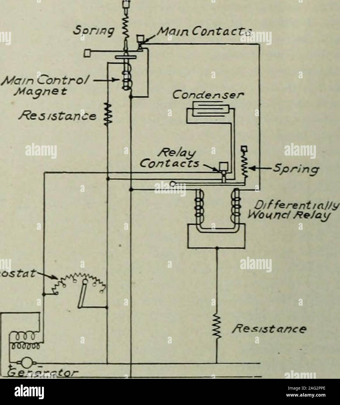
Electrical World Lternating Current Regulator A Shunt Circuit Across The Generator Field Rheostat And The Otheracross The Exciter Field Rheostat The Direct Current Regulator Consists Of A Main Control Magnetand Relay The Relay from c8.alamy.com The circuit for tone generator is shown in below diagram. So, if it has connected directly to a speaker, the generated sound will not have enough volume. This is a pulse generator circuits or standard astable multivibrator oscillator or free running circuit using ic555 timer, ne555, lm555.we use it for digital logic circuits. Below are some examples of typical applications. Browse honda generator diagrams below. The clock generator is made up of two sections: I believe that it would need to have a resistor, or potentiometer, between the motor and the generator. Here also the circuit is an astable multivibrator which generates a square wave signal around 3khz frequency.
The generator circuit breaker is driven by the digital output '2'.
The dashboard is supplied by the terminal blade 15/54 via a 5 amp fuse. For use with generators up to 12500 w rated at 50 a at 125/250 v. This is a pulse generator circuits or standard astable multivibrator oscillator or free running circuit using ic555 timer, ne555, lm555.we use it for digital logic circuits. Generator wiring diagram and electrical schematics: The generator circuit breaker is driven by the digital output '2'. It reveals the components of the circuit as streamlined forms, and the power and also signal connections in between the gadgets. Champion 5500 watt generator cotswoldwool co. Ecu = engine control :automatic engine start. The types discussed in the following paragraphs are typical of the more predominant ones in use. This schematic shows a variation of the adsr envelope generator with a 7555 timer ic. Most educational diagrams of the alternators for simplicity show a power producing coil spinning between two poles of a permanent magnet. An operational amplifier lm1458 is a dual purpose operational amplifier and the bias network and power supply lines of these dual operational amplifiers are common. Click on the link for your model number to open a.pdf version of the generator manual.
5 500 watt wheelhouse parts diagram for 6 exl wiring generac 4987 0 megaforce portable power systems 8 kw lp orenco control panel 4 000 generator kohler transfer switch 6500 linz 10 2008 0f6587 home standby milbank diagrams full schematic house 1939 ford pickup 7 briggs lookup 10kw 9067 user manual xl 06 96 9 3 stratton 30kw sn. An emp (or electromagnetic pulse) has the power to knock out all electronic devices within its range. Heavy duty power cord connector. So, if it has connected directly to a speaker, the generated sound will not have enough volume. This circuit is a tone generator using an op amp.
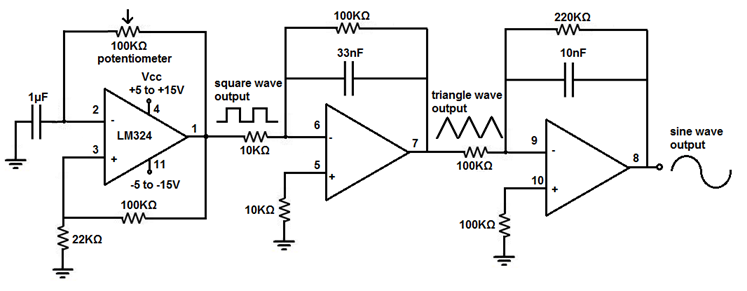
Function Generator Circuit Diagram Using Lm324 Ic Its Specification from www.elprocus.com Browse champion generator diagrams below. Reserves the right to change this publication and the products represented. The be24 generator auto start circuit diagram is a simple and intuitive diagram. However, they all perform the same basic function. Heavy duty power cord connector. Eng = engine only : Click on the link for your model number to open a.pdf version of the generator manual. So, if it has connected directly to a speaker, the generated sound will not have enough volume.
For use with generators up to 12500 w rated at 50 a at 125/250 v.
The clock generator is made up of two sections: These are my plans for an emp generator. The generator circuit breaker is driven by the digital output '2'. The parts list is as follows: This schematic shows a variation of the adsr envelope generator with a 7555 timer ic. For those interested in assembling the circuit shown here, fully functional firmware (a hex file) is available on the qex web page at www.arrl. The 741 op amp can deliver only a small output current. Below are some examples of typical applications. The four integrated circuits in the function generator circuit are ic 1a, ic 1b, ic 2a, and ic 2b. To filter out the noise from supply voltage capacitors are placed across terminals as shown in the diagram. The circuit for tone generator is shown in below diagram. An emp (or electromagnetic pulse) has the power to knock out all electronic devices within its range. The transfer switch is the device that transfers the power from the utilities power to the standby generators power, as shown in figure 1.